Cable entry filling pressure regulations
Sealing applications and filling pressure regulations for sealing elements
coated with swelling material or cellular rubber.
All products, with and without valve inflation technology.
- Screw the end cap onto the sealing element.
- Attach inflator hose (end D) to the automatic fill-stop (end C).
- Fig I: Attach end E to the valve and tighten with B, holding the valve extension immobile.
- Fig II: Turn part A in the clockwise direction.
- Pressure-fill the sealing element with air (CO2-neutral) using the cordless compressor and inflator
hose e.g. Art.-No. 33 BDC-S.
- The max. permissible filling pressure is printed on the packaging unit and on the sealing element itself.
- Fig III: Loosen part A (turning it in the anti-clockwise direction).
- Fig IV: Unscrew part B (anti-clockwise), holding the valve extension immobile, and remove the fill-stop valve.
- After inflation of the sealing element, the valve end cap must be screwed finger-tight onto the valve (lengthens service life).
Tightness of 0.5 bar is reached immediately on water entry.
Inflating sealing elements types 80 - 300
- Screw the valve end cap onto the sealing element.
- Inflate the sealing element with air (CO2-neutral) using the cordless compressor and inflator hose e.g. Art. No. 33 BDC-S or the equivalent.
- The max. permissible filling pressure is printed on the packaging unit and on the sealing element itself.
- After inflation of the sealing element, the valve end cap must be screwed finger-tight onto the valve (lengthens service life).
Tightness of 0.5 bar is reached immediately on water entry.
Requirements for inflation tools
- Filling capacity ≤ 20 litres/min
- Automatic pressure shut-off or 0 to 4 bar pressure gauge
- Accuracy of the pressure display in the 0.5-3.5 bar range at 20 °C (tolerance ± 0.1 bar)
- Please observe our safety instructions when using sealing
elements made of aluminium and synthetic material
composites.
SI 05 Part 1
Table 1 - Sealing areas & filling pressure
Art. No. |
| Duct ID [mm] | Sealing area configuration | Filling pressure | ||
Optimum [mm] | Minimum [mm] | [bar] | [psi] | |||
16.1 QAK/V 16.2 QAK/V 16.3 ZKAK/V 16.4 ZKAK/V 16.8 0-AK/V 19.1 SSB2 19.2 SSB2 19.3 ZKSB2 19.4 ZKSB2 19.8 0-SB2 20.3 ZKADE/V 20.4 ZKADE/V 20.5 QADE/V 20.6 QADE/V 20.8 0-DE/V | L 40 | 40 | 22 | 0 | 2,8 | 40.6 |
35 | 11 | 0 | ||||
L 45 | 45 | 32 | 0 | |||
40 | 27 | 0 | ||||
L 50 | 50 | 33 | 0 | |||
45 | 25 | 0 | ||||
L 60 | 60 | 42 | 0 | |||
50 | 26 | 0 | ||||
L 80 | 80 | 57 | 0 | |||
70 | 41 | 0 | ||||
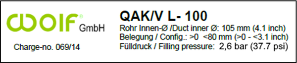
L 90 | 90 | 70 | 0 | 2,6 | 37.7 | |
80 | 55 | 0 | ||||
L 100 | 105 | 80 | 0 | |||
95 | 65 | 0 | ||||
L 115 | 115 | 89 | 0 | |||
105 | 70 | 0 | ||||
L 125 | 125 | 97 | 20 | 2,1 | 30.5 | |
115 | 82 | 10 | ||||
L 150 | 150 | 119 | 42 | 1,8 | 26.1 | |
140 | 104 | 32 | ||||
16.1 QAK/V 16.2 QAK/V 16.3 ZKAK/V 16.4 ZKAK/V | L 175 | 175 | 130 | 70 | 1,5 | 21.8 |
165 | 115 | 60 | ||||
155 | 105 | 50 | ||||
L 200 | 200 | 155 | 90 | 1,2 | 17.4 | |
190 | 140 | 80 | ||||
180 | 130 | 70 | ||||
L 225 | 225 | 175 | 120 | |||
215 | 160 | 110 | ||||
205 | 150 | 100 | ||||
L 250 | 250 | 190 | 140 | 1,1 | 16.0 | |
240 | 180 | 130 | ||||
230 | 170 | 120 | ||||
L 275 | 275 | 230 | 170 | 1,0 | 14.5 | |
265 | 215 | 160 | ||||
255 | 205 | 150 | ||||
L 300 | 300 | 250 | 190 | 0,9 | 13.1 | |
290 | 240 | 180 | ||||
280 | 225 | 170 | ||||
Group 16.1 and 16.2 QV swelling material coating 19.1 and 19.2 20.5 and 20.6
16.3 and 16.4 ZK cellular rubber coating 19.3 and 19.4 20.3 and 20.4
16.8 and 19.8 without coating 20.8
The values provided in table 1 for operational filling pressure are based on an ambient and operational temperature of 20 °C ± 5 °C.
Due to the physical properties of compressed air as a function of temperature, the filling pressure will change depending on the ambient and operational temperature.
For this reason, an adjustment of the filling pressure must be adapted to the current ambient or operating temperatures during installation.
| Filling pressure [bar | psi] at installational-/ambient temperature | |||||||
Sealing element type |
| -20 °C | -10 °C | 0 °C | +20 °C | +30 °C | +40 °C | +70 °C |
-4 °F | 14 °F | 32 °F | 68 °F | 86 °F | 104 °F | 158 °F | ||
QAK/V ZKAK/V
SSB2 ZKSB2
ZKADE/V QADE/V | L 40 | 2,4 bar / 34.8 psi | 2,5 bar / 36.3 psi | 2,6 bar / 37.7 psi | 2,8 bar / 40.6 psi | 2,9 bar / 42.1 psi | 3,0 bar / 43.5 psi | 3,3 bar / 47.9 psi |
L 45 | ||||||||
L 50 | ||||||||
L 60 | ||||||||
L 80 | ||||||||
L 90 | 2,2 bar / 31.9 psi | 2,3 bar / 33.4 psi | 2,4 bar / 34.8 psi | 2,6 bar / 37.7 psi | 2,7 bar / 39.2 psi | 2,8 bar / 40.6 psi | 3,1 bar / 45.0 psi | |
L 100 | ||||||||
L 115 | ||||||||
L 125 | 1,7 bar / 24.7 psi | 1,8 bar / 26.1 psi | 1,9 bar / 27.6 psi | 2,1 bar / 30.5 psi | 2,2 bar / 31.9 psi | 2,3 bar / 33.4 psi | 2,6 bar / 37.7 psi | |
L 150 | 1,4 bar / 20.3 psi | 1,5 bar / 21.8 psi | 1,6 bar / 23.2 psi | 1,8 bar / 26.1 psi | 1,9 bar / 27.6 psi | 2,0 bar / 29.0 psi | 2,3 bar / 33.4 psi | |
QAK/V ZKAK/V | L 175 | 1,1 bar / 16.0 psi | 1,2 bar / 17.4 psi | 1,3 bar / 18.9 psi | 1,5 bar / 21.8 psi | 1,6 bar / 23.2 psi | 1,7 bar / 24.7 psi | 2,0 bar / 29.0 psi |
L 200 | 0,8 bar / 11.6 psi | 0,9 bar / 13.1 psi | 1,0 bar / 14.5 psi | 1,2 bar / 17.4 psi | 1,3 bar / 18.9 psi | 1,4 bar / 20.3 psi | 1,7 bar / 24.7 psi | |
L 225 | ||||||||
L 250 | 0,7 bar / 10.2 psi | 0,8 bar / 11.6 psi | 0,9 bar / 13.1 psi | 1,1 bar / 16.0 psi | 1,2 bar / 17.4 psi | 1,3 bar / 18.9 psi | 1,6 bar / 23.2 psi | |
L 275 | 0,6 bar / 8.7 psi | 0,7 bar / 10.2 psi | 0,8 bar / 11.6 psi | 1,0 bar / 14.5 psi | 1,1 bar / 16.0 psi | 1,2 bar / 17.4 psi | 1,5 bar / 21.8 psi | |
L 300 | 0,5 bar / 7.3 psi | 0,6 bar / 8.7 psi | 0,7 bar / 10.2 psi | 0,9 bar / 13.1 psi | 1,0 bar / 14.5 psi | 1,1 bar / 16.0 psi | 1,4 bar / 20.3 psi | |
Example: Effects of unsuitable filling pressure
An unsuitable filling pressure can impair the transmission properties of the sealed cables and damage casing pipes, medium pipes, etc.
Diagram: Benchmarks „Change in sealing element filling pressure
depending on the ambient temperature“

Example: Measurement reports filling pressure
"Influence of ambient or operating temperature on the filling pressure inside the sealing cushion"
![[Translate to English:] Fülldruck-Messprotokolle „Einfluss der Umgebungs- oder Betriebstemperatur auf die Druckfüllung im Inneren der Abdichtkissen”](/fileadmin/_processed_/9/5/csm_Fuelldruck-Messprotokolle_-_Einfluss_der_Umgebungstemperatur_9e28cafa70.png)
Reasons why the filling pressure must be adapted to the current ambient or operating temperatures during installation.
Consequences of unreduced filling pressure at operational temperatures of -15 °C to +70 °C
Adaptation of filling pressure to ambient & operational temperatures
1. Ambient or operational temperature > +25 °C
Annular space sealing
(the sealing element is between the borehole/ outer casing duct and the plastic inner duct made of plastic):
Reduction of the prescribed filling pressure
by 0.5 bar as shown in Table 1 can prevent
the plastic inner casing tube from collapsing.

2. Ambient or operational temperature > +45 °C
Cable sealing
(the sealing element is between the borehole/ outer casing duct. the plastic inner duct made of plastic. and telecom cables):
Reduction of the prescribed filling pressure
by 0.5 bar as shown in Table 1

3. Operational temperature < +70 °C at cable sheath or duct (for local heating)
Cable sealing
Reduction of the prescribed filling pressure
(Table 1) by 0.8 bar can prevent buckling of
cable (5a) and/or microduct (5b) and bursting
of the cable seal.

4. Operational temperature < +70 °C at cable sheath or duct (for local heating)
Power cable acc. to DIN EN 61442 (short circuit):
Reduction of the prescribed filling pressure (Table 1)
by 0.8 bar can prevent buckling of cable (5a) and/or
icroduct (5b) and bursting of the cable seal.
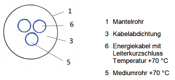
1 Outer casing duct
2 Transmission station etc.
3a Sealing cushion (valve)
16.1 and 16.2 QAK/V L
16.3 and 16.4 ZKAK/V L
16.8 0-AK/V L
20.3 and 20.4 ZKADE/V L
20.5 and 20.6 QADE/V L
20.8 0-DE/V L
3b Pliable metall valve extension
(with thread adhesive on the sealing cushion)
Art. No. 83.8 MSR-VV
5a Electrical and/or optical
telecommunication cables
5b Inner casing duct or power cable